Broadcom eCos | Reversing the OS Memory Layout

In this article I’ll explain my methodology to reverse the memory layout used by eCos, and more specifically by the Broadcom variant of eCos.
Our objective is to identify:
- any vector location (interrupt vectors, exception vectors, virtual vector table, etc)
- the .text section
- the .data section
- the .bss section
- the stack location
- the heap location
While it may not be quite clear now, documenting this will be helpful in the future. It will be a time saver when reversing firmware files given that you’ll have a clear memory map, and will provide the necessary background when thinking about exploitation.
We’ll go through each specific location one by one in the next sections.
Identifying Vectors Location
By reading the eCos source code for MIPS and doing some research into dedicated vectors, I identified the following locations:
| Vector/Table | Address |
|---|---|
| Common Vector | 0x80000000 |
| Stub Entry Vector | 0x80000100 |
| Debug Vector | 0x80000200 |
| Virtual Service Routine Table | 0x80000300 |
| Virtual Vector Table | 0x80000400 |
I advise you to go through the material on exception and interrupt vectors if you want to know more about the subject. It’s not a requirement for the rest of this article though.
Identifying the BSS section
During the boot sequence, eCos clears the .bss section. This action is executed by the hal_zero_bss function. That function is defined in ./packages/hal/mips/arch/v2_0/src/vectors.S, in pure MIPS assembly.
The function is reproduced below:
##-----------------------------------------------------------------------------
 ## hal_zero_bss
 ## Zero bss. Done in assembler to be optimal rather than using memset,
 ## which would risk zeroing bss while using it.

 FUNC_START(hal_zero_bss)
 #ifdef CYGHWR_HAL_MIPS_64BIT
 #define STORE_OP        sd
 #define BLOCK_SHIFT     6
 #else
 #define STORE_OP        sw
 #define BLOCK_SHIFT     5
 #endif
         la      a0,__bss_start          # start of bss
         la      a1,__bss_end            # end of bss
         andi    a2,a0,mips_regsize-1    # is bss aligned?
         bne     a2,zero,1f              # skip word copy
         nop

         # loop with 8 stores per loop
         subu            a3,a1,a0                # get length
         srl             a3,a3,BLOCK_SHIFT       # get number of blocks
         sll             a3,a3,BLOCK_SHIFT       # get length of blocks
         addu            a3,a0,a3                # get end addr of blocks
 2:      STORE_OP        zero,(mips_regsize*0)(a0)
         STORE_OP        zero,(mips_regsize*1)(a0)
         STORE_OP        zero,(mips_regsize*2)(a0)
         STORE_OP        zero,(mips_regsize*3)(a0)
         STORE_OP        zero,(mips_regsize*4)(a0)
         STORE_OP        zero,(mips_regsize*5)(a0)
         STORE_OP        zero,(mips_regsize*6)(a0)
         STORE_OP        zero,(mips_regsize*7)(a0)
         addu            a0,a0,mips_regsize*8    # next addr
         bne             a3,a0,2b                # to next store
         nop

         # If length is a multiple of block size then we
         # are done and need to skip the byte loop
         beq     a1,a0,3f
         nop

         # finish 1 byte at a time
 1:      sb      zero,0(a0)              # zero memory
         addiu   a0,a0,1                 # next addr
         bne     a0,a1,1b                # to next store
         nop
 3:      jr      ra
         nop
 FUNC_END(hal_zero_bss)
To us, the most important bits of information from the assembly are that the code loads the start address of .bss (__bss_start) into register $a0 and the end address of .bss (__bss_end) into register $a1.
Let’s look at actual firmwares to see what it looks like. On a Netgear firmware, we see that it starts with:
hal_zero_bss
80004854 3c 04 81 61     lui        a0,0x8161
80004858 24 84 68 c8     addiu      a0,a0,0x68c8
8000485c 3c 05 81 b5     lui        a1,0x81b5
80004860 24 a5 25 70     addiu      a1,a1,0x2570
80004864 30 86 00 03     andi       a2,a0,0x3
80004868 14 c0 00 12     bne        a2,zero,LAB_800048b4
8000486c 00 00 00 00     _nop
So for that firmware, we know that __bss_start is set to 0x816168c8 and __bss_end to 0x81b52570.
Another example, this time with an ASKEY firmware:
hal_zero_bss
80004854 3c 04 81 97     lui        a0,0x8197
80004858 24 84 9f 48     addiu      a0,a0,-0x60b8
8000485c 3c 05 81 bc     lui        a1,0x81bc
80004860 24 a5 89 a0     addiu      a1,a1,-0x7660
80004864 30 86 00 03     andi       a2,a0,0x3
80004868 14 c0 00 12     bne        a2,zero,LAB_800048b4
8000486c 00 00 00 00     _nop
Here, __bss_start is equal to 0x819760b8 and __bss_end is equal to 0x81bc7660.
We discovered that hal_zero_bss always starts at the same offset (0x80004854), regardless of the firmware vendor. This is due to the way eCos compilation works and the fact that hal_zero_bss is defined before eCos packages or external libraries.
Given an arbitrary firmware file, we should be able to auto-identify the start and end locations of the .bss section by seeking to that offset and matching on the instructions setting registers $a0 and $a1.
We developed the Python 3 script below to do so:
#!/usr/bin/env python3
import re
import sys
import struct

offset = 0x854 # 0x80004854 - load_address 0x80004000
flirt = re.compile(b"\x3c\x04([\x00-\xFF][\x00-\xFF])\$\x84([\x00-\xFF][\x00-\xFF])\x3c\x05([\x00-\xFF][\x00-\xFF])\$\xa5([\x00-\xFF][\x00-\xFF])\x30\x86\x00\x03\x14\xc0\x00\x12")

fp =  open(sys.argv[1], 'rb')
fp.seek(offset)
instruction = fp.read(24)
match = flirt.findall(instruction)
if match:
    a0_upper = struct.unpack(">H", match[0][0])[0]
    a0_lower = struct.unpack(">H", match[0][1])[0]
    a1_upper = struct.unpack(">H", match[0][2])[0]
    a1_lower = struct.unpack(">H", match[0][3])[0]
    a0 = (a0_upper << 16) + a0_lower
    a1 = (a1_upper << 16) + a1_lower
    print("__bss_start: 0x{:0x}\n__bss_end: 0x{:0x}".format(a0, a1))
fp.close()
To confirm our assumption, we ran the code on 7 other firmwares (on top of the Netgear and ASKEY ones). We successfully identified the .bss start and end address on each of them.
find firmwares -name "*out" -print -exec python3 identify_bss.py {} \;
firmwares/bcm2-dumps/epc3008/e3000-c1000r5593-150723c.out
__bss_start: 0x80789f78
__bss_end: 0x808a24b0
firmwares/bcm2-dumps/tc7200/TC7200.out
__bss_start: 0x814e3928
__bss_end: 0x819cb190
firmwares/bcm2-dumps/twg870/TWG870U-BA.out
__bss_start: 0x812b5260
__bss_end: 0x815e2da0
firmwares/bcm2-dumps/twg850/TWG850-4U-9D.out
__bss_start: 0x80b7e800
__bss_end: 0x80e24770
firmwares/bcm2-dumps/c6300bd/C6300BD_1TLAUS_V1.out
__bss_start: 0x814bf3f8
__bss_end: 0x816e0560
firmwares/bcm2-dumps/cbw383zn/CBW-383ZN-0081.out
__bss_start: 0x8173fb90
__bss_end: 0x81bda4a0
firmwares/bcm2-dumps/fast3890/FAST3890_TLC_50.out
__bss_start: 0x80db1e30
__bss_end: 0x81313190
These firmware were downloaded and extracted from https://github.com/jclehner/bcm2-dumps/.
Identifying .data section
From cursory analysis of multiple eCos based Broadcom firmwares, we identified that the data section always starts with the string “bcm0”. Given that the .data section is at the end of the firmware file, it ends with a large amount of null bytes.
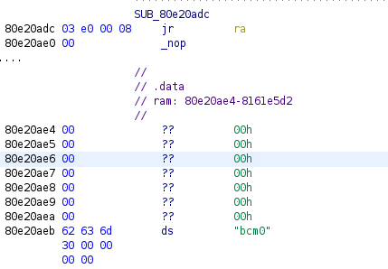
Here is the start of the .data section of an ASKEY firmware:
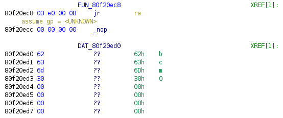
Here is the start of the .data section of a Netgear firmware, manually defined:
We can therefore identify the beginning and end of .data section with a script like the one below:
DEFAULT_LOAD_ADDRESS = 0x80004000
fp =  open(sys.argv[1], 'rb')
s = fp.read()
fp.close()

data_start_offset = s.find(b"\x00\x00\x00\x00bcm0\x00\x00\x00\x00")
data_end_offet = s.find(b"\x00" * 2000)
data_start = DEFAULT_LOAD_ADDRESS + data_start_offset
data_end = DEFAULT_LOAD_ADDRESS + data_end_offset
print("__data_start: {:0x}".format(data_start))
print("__data_end: {:0x}".format(data_end))
Similarly to the .bss section identification, we ran the script on a bunch of other firmware files and obtained valid results.
Identifying Stack Location
We initially identified the stack start address by executing this command from the CM shell of a live device:
CM> taskShow

  TaskId               TaskName              Priority   State
---------- --------------------------------  --------  --------
0x8195c730           Network alarm support       6       SLEEP
0x818dadd8                 Network support       7       SLEEP
0x81960ef0                pthread.00000800      15        EXIT
0x81753c48                        tStartup      18       SLEEP
0x87e7754c      NonVol Device Async Helper      25       SLEEP
0x818d8088                     Idle Thread      31         RUN
0x87e35c44           LED Controller Thread      23       SLEEP
0x87e34458     Reset/Standby Switch Thread      23       SLEEP
0x87e2fbd0            Foxconn Timer Thread      23       SLEEP
0x87e1e1cc             eRouter Ping Thread      29       SLEEP
0x87e7dd1c                            WDOG      17       SLEEP
0x87d1b3c8                    CfgVB Thread      23       SLEEP
The first task is tStartup and its dedicated stack zone starts at 0x81753c48, which is the lowest address of the list.
We obtain similar results with the command ‘stackShow’:
CM> stackShow

                                                                   Stack     Stack    Stack
  TaskId               TaskName              Priority   State      Size      Used     Margin
---------- --------------------------------  --------  --------  --------  --------  --------
0x8195c730           Network alarm support       6       SLEEP     5328      1424      3904
0x818dadd8                 Network support       7       SLEEP     8192       760      7432
0x81960ef0                pthread.00000800      15        EXIT     7804      1216      6588
0x81753c48                        tStartup      18       SLEEP    12288      9784      2504
0x87e7754c      NonVol Device Async Helper      25       SLEEP     3072       500      2572
0x818d8088                     Idle Thread      31         RUN     2048      1064       984
0x87e35c44           LED Controller Thread      23       SLEEP     4096       900      3196
tStartup is always the first thread to be created on the Broadcom platform. Therefore, this thread’s stack base address will be the system’s stack base address.
The launch of tStartup is performed by calling cyg_thread_create, the assembly is provided below:
3c 07 80 fc     lui        a3,0x80fc
24 e7 03 34     addiu      a3=>s_tStartup_80fc0334,a3,0x334                 = "tStartup"
3c 08 81 74     lui        t0,0x8174
25 08 7c 48     addiu      t0,t0,0x7c48
24 09 30 00     li         t1,0x3000
3c 10 81 75     lui        s0,0x8175
26 0a 3d 70     addiu      t2,s0,0x3d70
3c 0b 81 75     lui        t3,0x8175
0c 34 d1 0a     jal        cyg_thread_create                                undefined cyg_thread_create()
25 6b 3c 48     _addiu     t3,t3,0x3c48
cyg_thread_create signature follows:
void cyg_thread_create
(
  cyg_addrword_t     sched_info,  /* scheduling info (priority) */
  cyg_thread_entry_t *entry,      /* thread entry point         */
  cyg_addrword_t     entry_data,  /* entry point argument       */
  char               *name,       /* name of thread             */
  void               *stack_base, /* pointer to stack base      */
  cyg_ucount32       stack_size,  /* size of stack in bytes     */
  cyg_handle_t       *handle,     /* returned thread handle     */
  cyg_thread         *thread      /* space to store thread data */
)
Instead of using registers $a0 to $a3 for parameters, and then the stack to store subsequent parameters, the Broadcom platform use an interesting convention which consists of putting parameters in registers $a0 to $a3, then $t3, $t1, $t2, and $t0.
Given cyg_thread_create signature, we’re interested in the value put in register $t3 which corresponds to the pointer to the base of the stack (stack_base), along with the value put in register $a3, which is a pointer to a string holding the thread’s name (“tStartup”).
We can auto-identify the stack start address of any Broadcom firmware by following these steps:
- identifying the string “tStartup” in the binary
- cross-reference that string to a location where it is loaded into register $a3
- from there, match instructions setting register $t3 value. That value is the stack start address.
Identifying Heap Location
We can obtain information about the heap by going into HeapManager menu and typing stats:
CM> cd HeapManager
CM/HeapManager> stats


BcmHeapManager basic statistics:
      Initial heap size:  104528528 bytes
            Free memory:  75084260 bytes
          Largest block:  74433844 bytes
              Low water:  74433844 bytes

              Node size:  12 bytes
     Nodes on free list:  17
    Nodes on alloc list:  103276

            Alloc fails:  0 (not enough memory)
             Free fails:  0 (invalid memory pointer)

        Region[0] start = 0x81b52570
          Region[0] end = 0x87f01ff4 (with overhead)

BcmHeapManager:  BCM_HEAP_BOUNDS_CHECK is compiled out, so these counters will report 0!

BcmHeapManager BoundsChecking stats:

Counter             Value      Notes
---------------- ------------  ------------------------------------------------
AllocsCorrupt               0  Memory corruptions detected during malloc/realloc
FreeCorrupt                 0  Memory corruptions detected during free/realloc
BCheckCorrupt               0  Memory corruptions found during bounds check
NodeCorruptRecov            0  Corrupted nodes found during bounds check that could be recovered or fixed
NodeCorruptFatal            0  Corrupted nodes found during bounds check that could not be recovered or fixed.Memory corruptions occur when a non-seed value (0xcd) is detected in an area
that should be seeded.  For free memory being allocated, this is any memory
anywhere in the buffer; for allocated memory being freed, this is the buffer
zone at the front or back of the buffer that was seeded.  During a bounds
check, this is all of the above.

Node corruption includes unexpected values in the fields of the structures
that track allocated and free memory.
It may not be obvious, but the heap start address (0x81b52570) is precisely the address where the .bss section ends.
What’s left is to identify where the heap ends. The initial heap size is 104528528 size, it’s close enough to 100MB (104857600 bytes) so let’s just consider the heap is 100MB.
Understanding how heap allocation works on eCos will be the subject of a dedicated article.
Putting Everything Together
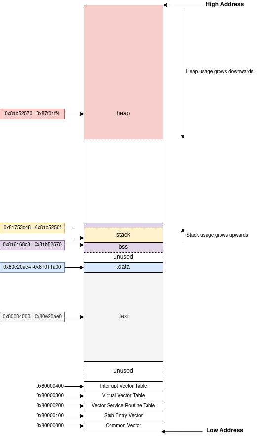
Now that we documented the most interesting locations in the memory, let’s put everything together to have a better understanding.
The diagram below presents the whole memory used by a running device. If I’m not mistaken, there should be a dedicated stack for interrupts just below the BSS section. This region is 4096 bytes long by default. Something I still need to look into.
Thanks to everyone on the corelan slack channel for the nice debate about high addresses/low addresses locations, and whether a stack actually “grows” or not :)
I also implemented all the auto identification procedure in a Python 3 script. It’s not relying on any decompiler or disassembler library so you will get results instantly. You can get it from the dedicated repository.
python3 memory_map.py firmware.decompressed.bin
.text start: 0x80004000
.text end: 0x80e20ae0
.text length: 0xe1cae0
.data start: 0x80e20ae4
.data end: 0x81011a00
.data length: 0x1f0f1c
.bss_start: 0x816168c8
.bss_end: 0x81b52570
stack start: 0x81753c48
stack end: 0x81757c48
Memory Permissions
From experience, this platform does not enforce any kind of permission flags on memory segments. The whole memory is read-write-execute.
Conclusion
In this article, we demonstrated how to reverse engineer the memory layout of the Broadcom variant of eCos.
Understanding the exact memory layout of a target is useful for exploitation and custom code injection. Now that we can identify memory regions, we know where we can write shellcode without interfering with the running system.
As always, if you have any question feel free to contact me via Twitter or email.
Tagged #ecos, #memory, #reversing.